
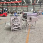

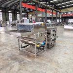
Combined Poultry Scalding & Plucking Machine
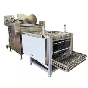
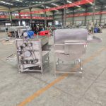
The combined poultry scalding and plucking machine consists of a self-discharging mixing scalding tank and a small plucking machine. It is mainly used for scalding and feather removal during poultry slaughtering. This product is especially suitable for small-scale processing plants, farmers' markets, and individual operators.
Contact Us for Pricing
Interested in this product? Contact us now for detailed pricing and product information.
Product Details
Product Introduction: Combined Poultry Scalding & Plucking Machine
I. Product Overview
The combined poultry scalding and plucking machine consists of a self-discharging mixing scalding tank and a small plucking machine. It is mainly used for scalding and feather removal during poultry slaughtering. This product is especially suitable for small-scale processing plants, farmers’ markets, and individual operators.
Made of stainless steel, the product features beautiful appearance, economical durability, energy saving, and stable performance. It has been well received by domestic and international customers since its launch.

II. Product Combinations
Two combinations are available to meet different user requirements:
| Combination Type | Composition | Application |
|---|---|---|
| Combination 1 | Self-discharging mixing scalding tank + Small 9-roller plucking machine | Larger production capacity |
| Combination 2 | Self-discharging mixing scalding tank + Small 7-roller plucking machine | Moderate production capacity |
The following introduction is based on Combination 1 (Self-discharging mixing scalding tank + Small 9-roller plucking machine) .
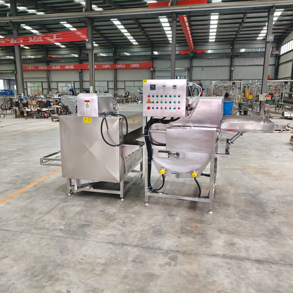
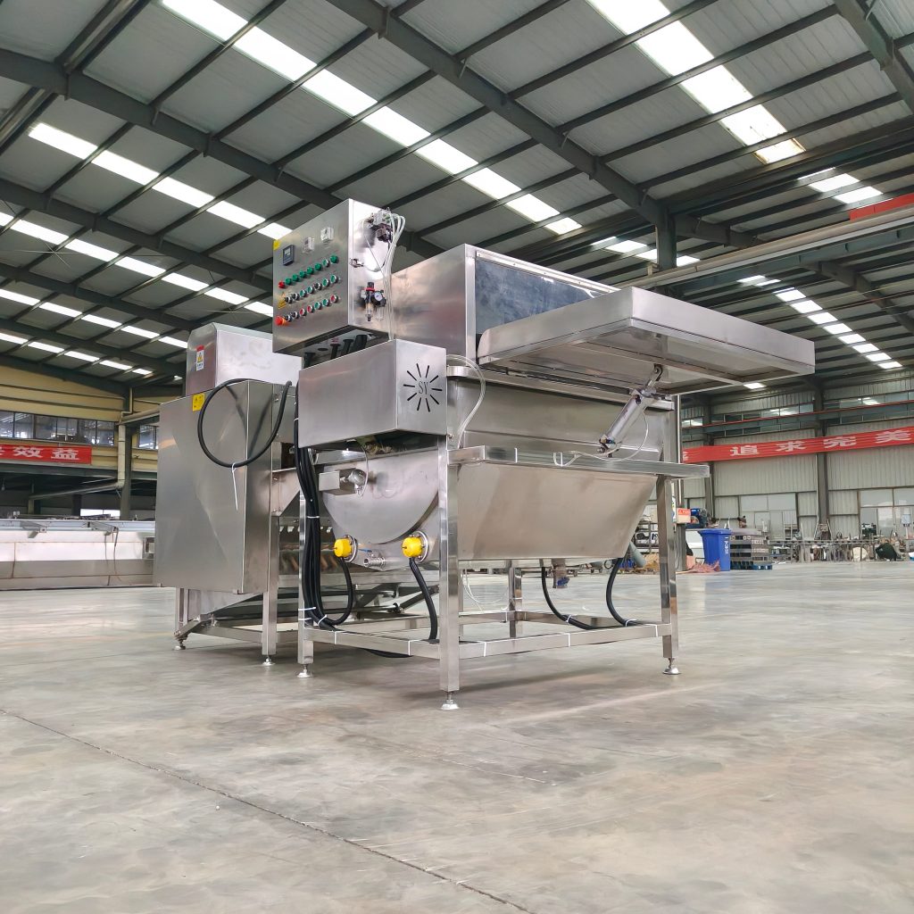
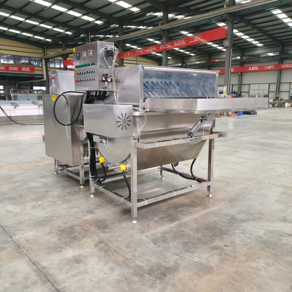
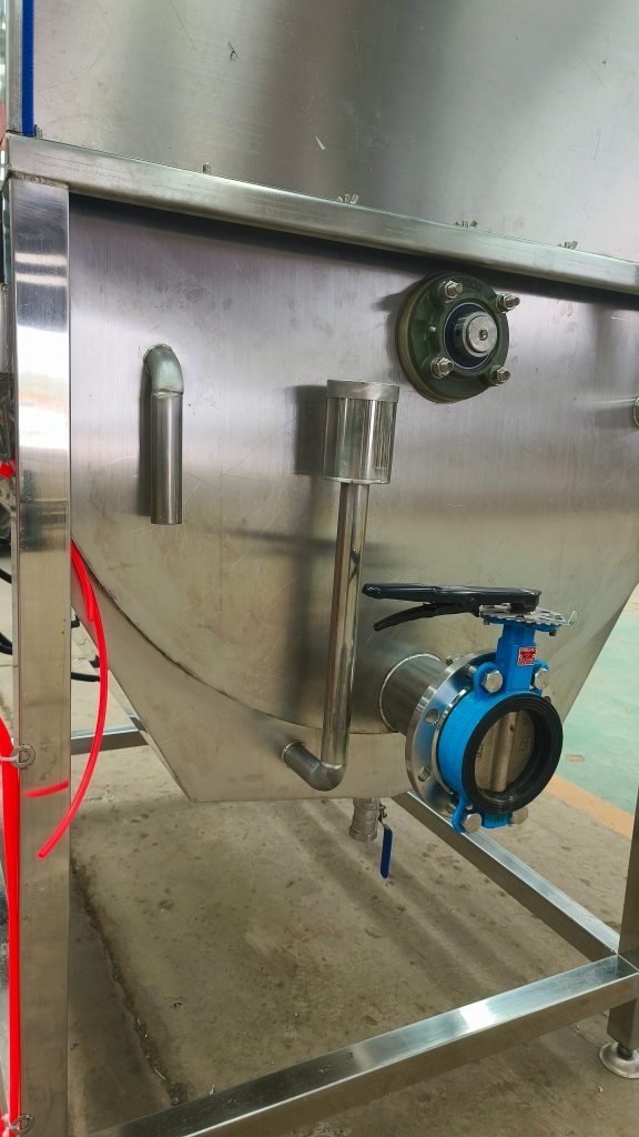
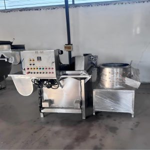
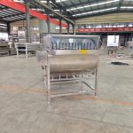
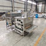
III. Self-Discharging Mixing Scalding Tank
1. Structural Features & Working Principle
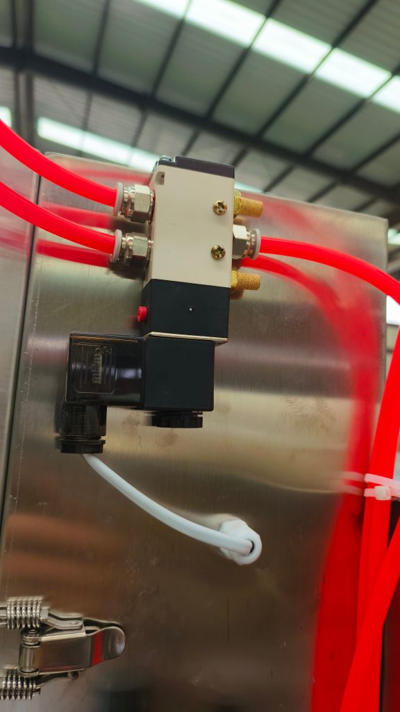
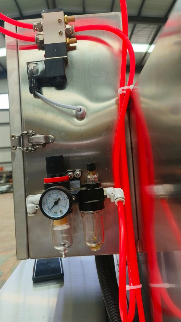
The scalding tank is equipped with steam heating pipes and electric heating devices at the bottom. For electric heating, thermal oil is used as the medium – the electric heating tubes heat the thermal oil, which then heats the water in the tank. For steam heating, the water is heated directly through steam pipes.
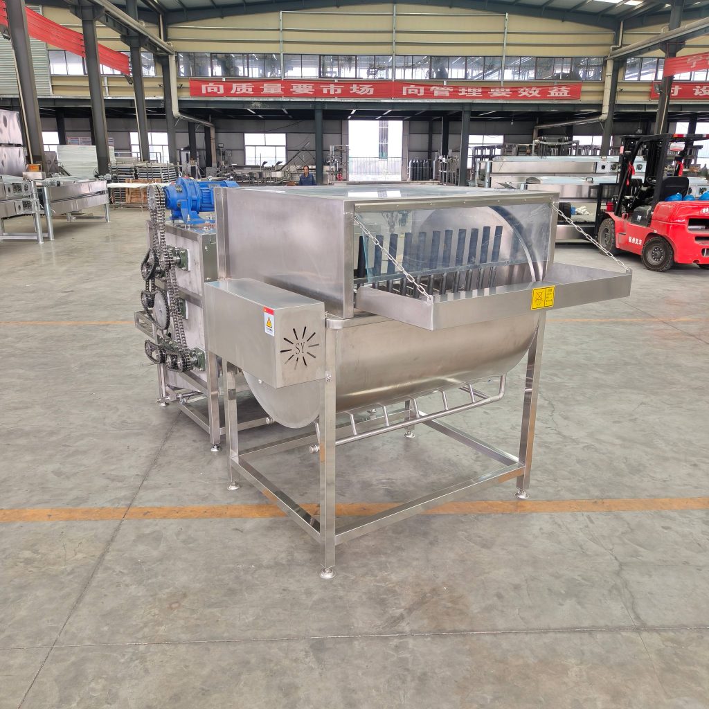
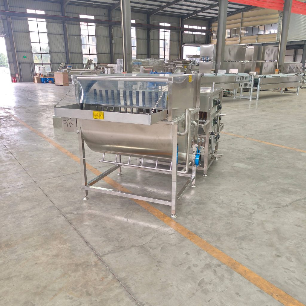
A main shaft with rubber bars and paddle-type lifters is installed in the middle of the tank. The operation is controlled via the electrical control panel:
- Main shaft rotates counterclockwise (scalding mode) : The poultry is scalded. The paddle-type lifters and rubber bars stir the water to ensure uniform scalding temperature.
- Main shaft rotates clockwise (discharging mode) : The scalded poultry is flipped out of the tank by the paddle-type lifters and transferred into the small plucking machine for feather removal.
2. Main Technical Parameters
| Parameter | Specification |
|---|---|
| Overall dimensions (L×W×H) | 1780 × 1600 × 1650 mm |
| Scalding temperature | 58–61°C |
| Input voltage | 380V / 50Hz |
| Power | (15×2 + 1.5) kW |
| Control mode | Manual / Automatic |

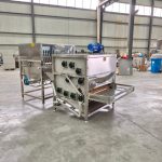
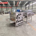
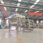
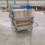
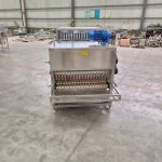
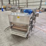
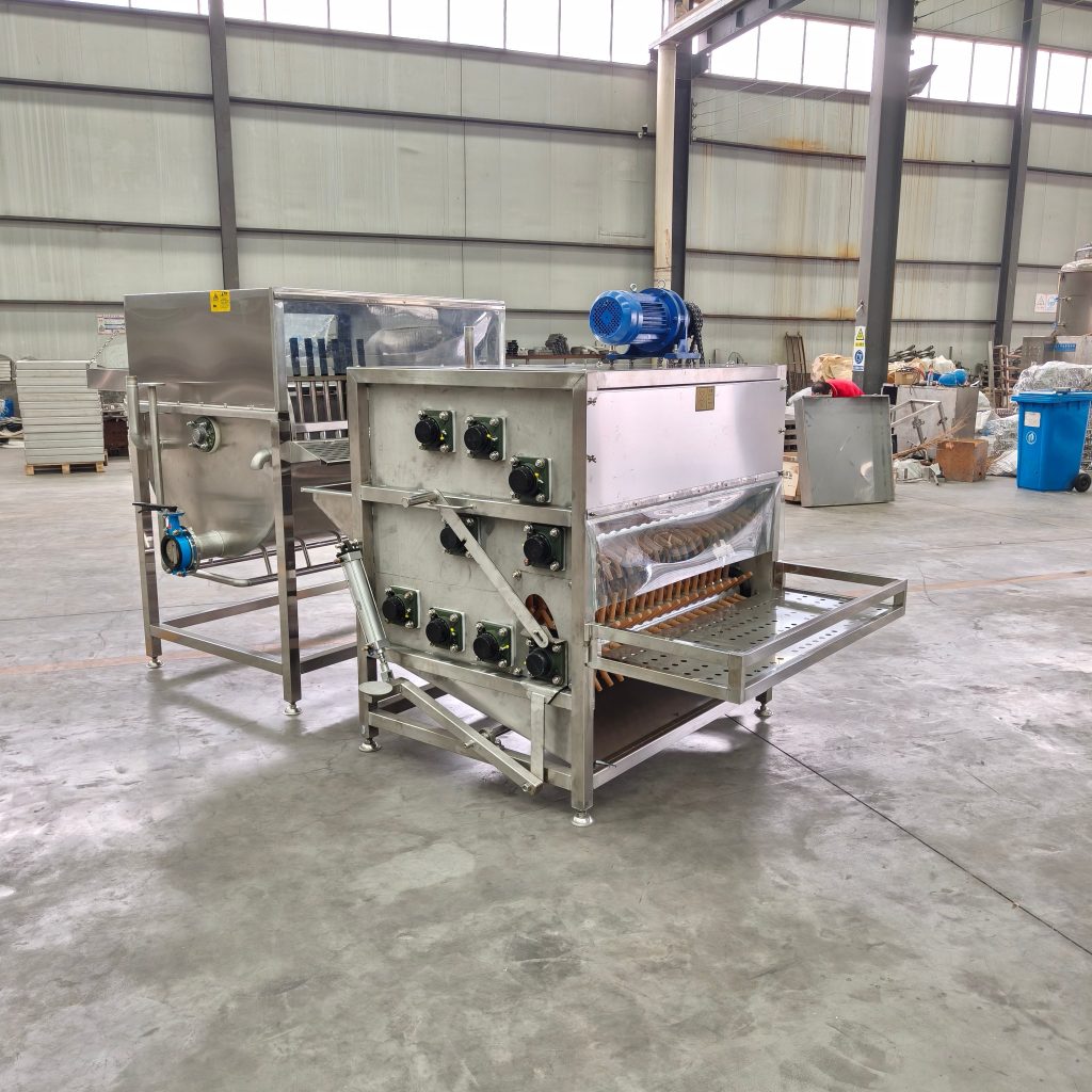
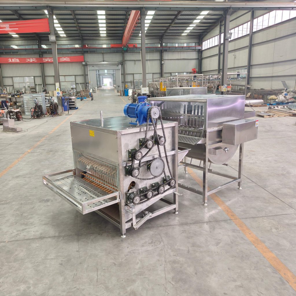
IV. Small 9-Roller Plucking Machine
1. Structural Features & Working Principle
The small 9-roller plucking machine (commonly called “small 9-roller”) consists of a frame, plucking rollers, drive unit, electrical control box, discharge chute, and feather collecting hopper. It is especially suitable for small-scale poultry slaughterhouses and individual operators.
The roller structure features a central main shaft with eight driven rollers arranged in a C‑shape around it, all driven by a single power source. Since the main and driven rollers rotate in the same direction, different sprocket sizes are used to adjust their rotational speeds, enabling simultaneous feather removal and forward movement of the poultry.
During operation, the set of rollers near the discharge outlet is positioned upward to prevent poultry from moving forward prematurely. After the feathers are completely removed, the operator steps on a pedal to lower the rollers, releasing the defeathered poultry. Therefore, the machine works in batches; the number of birds processed per batch depends on the poultry type.
2. Main Technical Parameters
| Parameter | Specification |
|---|---|
| Overall dimensions (L×W×H) | 1850 × 1650 × 1700 mm |
| Control mode | Manual / Automatic |
| Power | 2.2 kW |
| Plucking rubber finger specification | Type 95 |
V. Installation & Commissioning
1. General Installation Procedure
- Place the scalding and plucking machine in the designated position according to the drawings and the customer’s site conditions.
- Level the machine and adjust the anchor bolts so that all supports bear load evenly and the machine is stable.
- Connect the water supply pipe to the customer’s water mains.
- Connect the steam inlet pipe to the customer’s steam network (for steam heating users only).
- Install the electrical control box in a convenient, safe, and standard-compliant location.
- Check the electrical components inside the control box for damage; verify that the motor power matches the control circuit.
- A certified electrician should connect the main power and check the circuit according to the wiring diagram; verify that the motor rotation direction matches the indicated direction.
- Check the water and steam pipes for leaks; repair any leaks or poor sealing immediately.
2. Service
Installation, commissioning, and after‑sales service can be carried out either by our company’s professional technicians or by the user under remote guidance from our customer service.
VI. Safe Use & Precautions
1. Before Use
- Read the instruction manual carefully before use to understand the basic structure and working principle.
- Before each shift, fill the scalding tank with an appropriate amount of clean water and heat it to the set temperature.
- Start the motor and other drive units before poultry enters the machine; allow them to run idle for at least 1 minute.
2. Operational Safety
- Do not touch the machine while it is running.
- Do not insert hands or any objects into the machine during operation.
- Do not touch cables, wires, heating tubes, or other live or high‑temperature parts.
- Only trained personnel are allowed to adjust or operate the machine.
- If there is no automatic water level controller, water must be added manually. A dedicated person must be in charge of the machine; multi‑person operation is prohibited.
3. Safety Pictograms
| Symbol | Meaning |
|---|---|
| Danger | Electric shock hazard |
| Danger | Sharp object hazard |
| Danger | Rotating parts hazard |
| Warning | Hearing protection must be worn |
| Warning | Dust protection |
| Warning | Do not rotate equipment during repair |
4. Daily Maintenance
Self-discharging mixing scalding tank:
| Frequency | Task |
|---|---|
| Every shift | Check for wear, cracks, and smooth operation of transmission parts |
| Every shift | Check all fasteners for looseness |
| Every month | Fill bearings with lithium grease |
| Every 2 months | Replace seals to prevent leakage |
| Every 2 months | Replace rubber bars according to wear condition |
Small 9-roller plucking machine:
| Frequency | Task |
|---|---|
| Every shift | Check fasteners for looseness; tighten if necessary |
| Every 2 weeks | Replace rubber plucking fingers (frequency depends on throughput) |
| Every month | Add lithium grease to bearings |
| Every 6 months | Replace drive belts |
VII. Simple Troubleshooting
Self-discharging mixing scalding tank
| Problem | Cause | Solution |
|---|---|---|
| Electric heating tube does not work | Heating tube burnt; circuit disconnected | Replace heating tube; check and restore circuit |
| Water leakage at shaft end | Seal damaged | Replace seal |
Small 9-roller plucking machine
| Problem | Cause | Solution |
|---|---|---|
| Sudden stop during operation | Motor stopped; chain detached; bearing housing seized | Check power supply and connections; check drive belt; check bearing housing |
| Poor plucking effect | Rubber fingers worn or missing; improper gap, height, or angle | Replace rubber fingers; adjust working box height, gap, and angle |
| Abnormal noise during operation | Bearings or other rotating parts damaged | Replace damaged parts |
| Machine vibrates during operation | Fasteners loose; anchor bolts unevenly adjusted | Check and tighten fasteners; adjust anchor bolts |